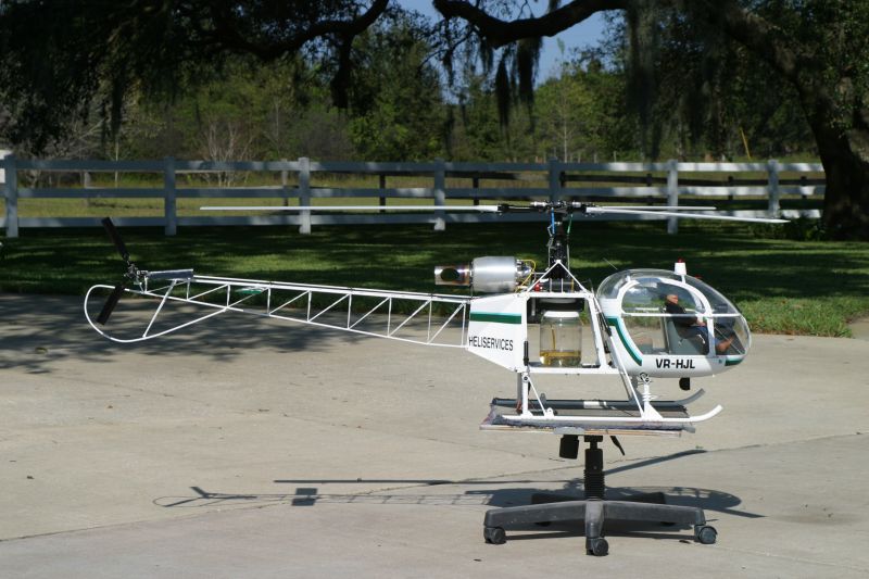

After the very successful flights of my prototype turbine Lama it comes time to start seriously preparing something for Top Gun 2003 and this machine is a prime candidate. Following my thought processes on the Nat's Lama, I went through a similar analysis procedure with this one. It has a number of things going for it, not the very least the superb flying characteristics of that magnificent 3 blade head. The basic helicopter is the Hirobo Big Lama in 1/5 scale. Added to it is the Jakodofsky turbine for a power plant. The first thing to do was to take a trip to Kinkos and blow up my engineering drawings of the Lama to 1/5 scale and see where the Hirobo kit deviated from scale if anywhere.
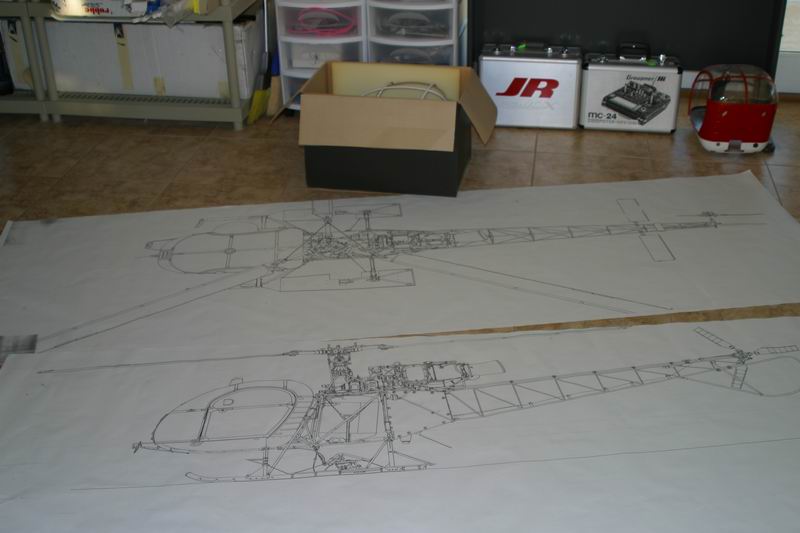
There are a number of discrepancies, some serious, most not. Starting from the front, the cabin is superb. The navigation lights on it are wrong and the seats inside are wrong. The instrument binnacle and controls are perfect. The landing gear is perfect as well. The center chassis is all wrong. The tailboom has minor errors like not enough bearings for the driveshaft. The tailrotor gearbox works superbly, but has a push rod to operate it whereas the full size is cable operated. The kit does contain the cables though. I wonder how many marks I would gain for making the enormous effort to have it cable operated? The main rotor head is very good, except for the Hirobo Logo cast in it and the color. Minor details have been missed off but the working dampers are beautiful and contribute much to the flying ability. Nothing very serious to worry about except this center section.
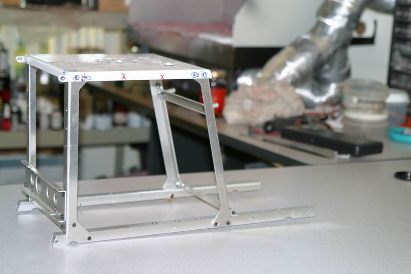
This should all be made out of tubular steel. There is no way I can convince the judges that this is correct so I will need to make one from tubular stainless steel. The original kit uses the mighty 3500BGX single cylinder 35cc glow motor for power and it is mounted to the bottom two rails by six 5mm bolts. The transmission goes up to the top plate where the main gear is mounted under the mast. Thus that whole area needs to be made out of the large gauge aluminum extrusions that it is, simply to survive the pounding and enormous torque from that 4HP glow motor.
As I am going to fit a turbine, I don't have to worry about that. Looking at the whole design, which is a bit difficult as its in my head right now, I see that all of the force will go though the top plate. I intend to make a top bearing mount for the mainshaft, which will bolt through the top plate to the mast. Thus all of the torque will be transmitted at this point. It obviously needs to be countered by the tailboom so the top plate to the tail rotor needs to be as rigid an assembly as possible. This means that the section under the mast need only support the cabin and take the load from the landing gear in the event of a heavy touch down. Because of this, I have decided to build the main cube frame from 3/8" tubing and the support struts from 1/4" tubing. Everything not directly silver soldered will have a stainless steel slug brazed into the end of the tubing for attaching bolts and I intend to tap as many holes as possible and not use nuts unless I have no choice.
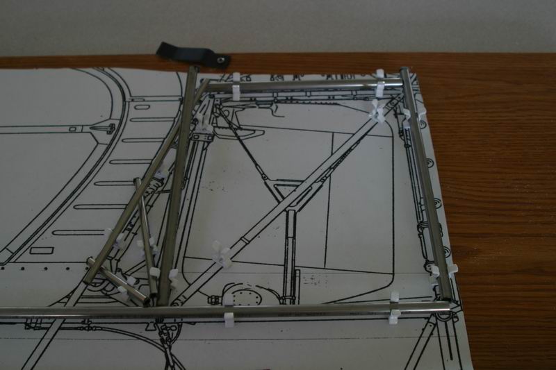
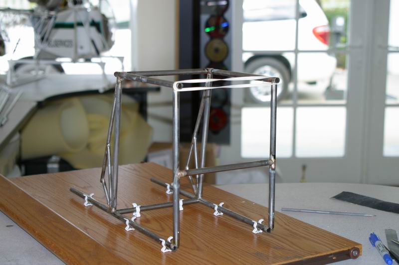
A trip to Kinkos and 10 minutes on their wondrous machine had a 1/5 scale set of engineering drawings. I cut out the center section and fixed it to a firm board with spray glue. Then I drilled holes to mount 3/8"tool clips which will hold the 3/8" tubing and 1/4" tool clips for the 1/4" tubing. The picture shows the tubing put in place before fitting. Each end of each tube had to be cut to the exact shape of the parts it was to fit to before brazing it together. Despite putting down sheets of aluminum the paper got burnt and the plastic around the tool clips melted, so there is no picture of the finished parts in the jig.
Then I made up another jig to hold the finished sideframes in place while I brazed the horizontals in position. Lots of filing and use of the try square was needed her to ensure perfect squareness with everything
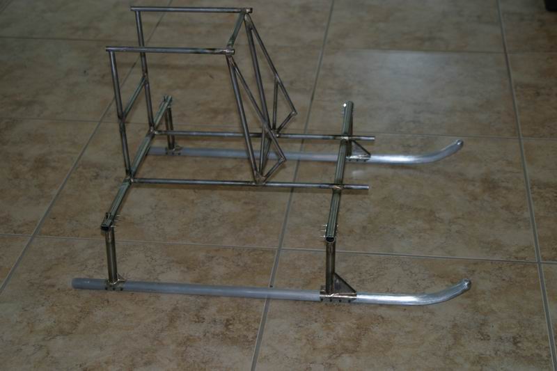
Finally I bit the bullet and used some parts from the new kit. The landing gear was assembled and brazed to the frame. This is necessary as I need to compare the position of the tailboom with the finished model to get the right position for the tailboom supports. This will be the most difficult part of the job and alignment will be critical. This frame is totally rigid. There is no flex in it at all and with angle tubes across the sides to be fitted and a top and bottom plate plus two end plates at the rear I don't expect any flex to develop in it ever. However, with the landing gear brazed to the frames, heavy landings will be expensive needing to have the landing gear unbrazed if it gets bent.
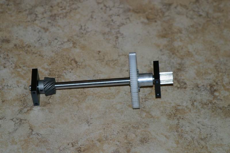
The engine has arrived and its in kit form this time, just how I wanted it. The first thing which has to be done is to make up the layshaft. This requires cutting to length, a flat grinding on it at each end and then some spacers making up for the main gear. It has to sit in the center of its slot.
Once everything lines up, the side frames are cut to size and fitted
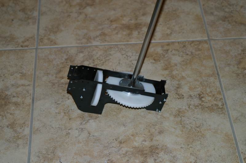
Then the next part to fit is this. Its a machined part which exercised all of my very limited skills on the lathe and mill. It was a question of lining everything up once and keeping it perfectly in alignment during all of the operations. Once its done, everything revolves around it and it locates all of the other parts.
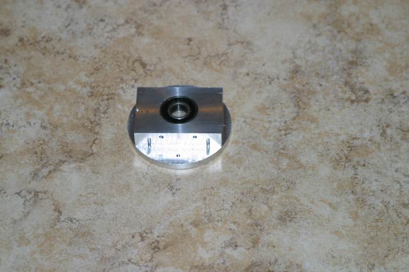
I fitted it into place and then machined the top surface down until the top plate was exactly the right height above the tail output drive. This was critical to the alignment of the tailboom
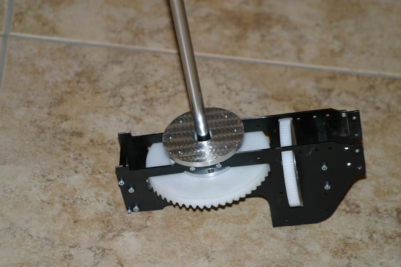
Top plate fitted with the mast housing lines everything up
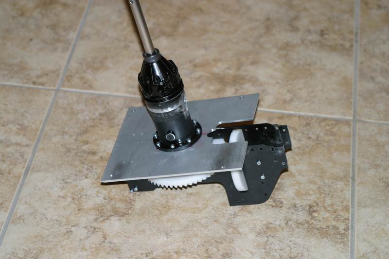
The surface has been cut down to take the nose of the engine into it and then roughened up ready for painting. The tail drive gear is fitted and checked for alignment
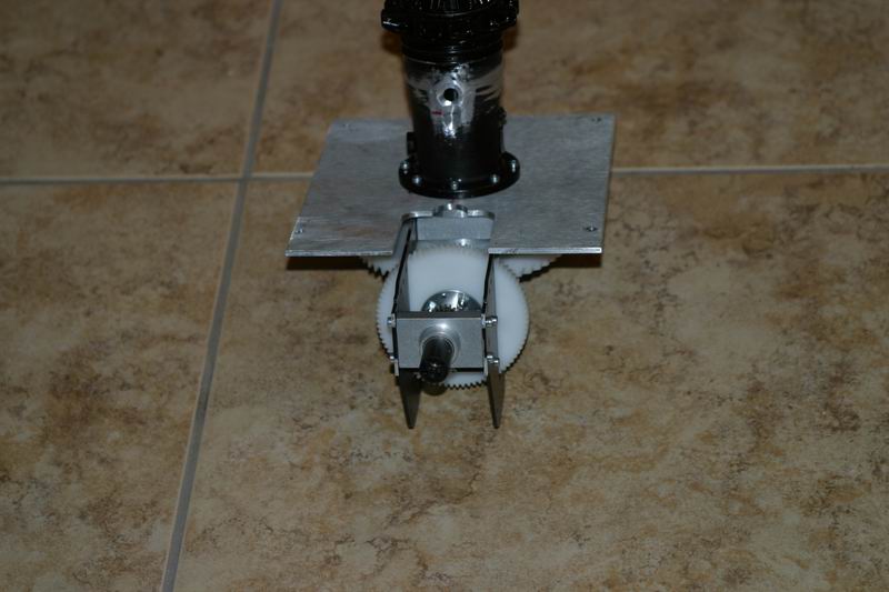
Then its time to fit the turbine and check that for alignments as well.
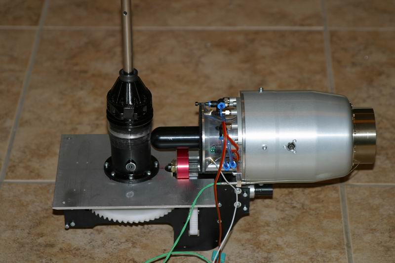
Now the top plate can be fitted to the frames
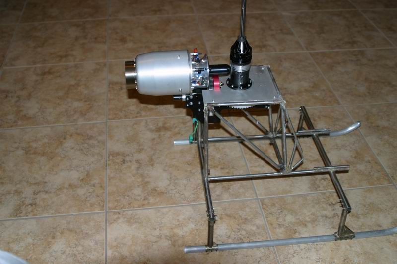
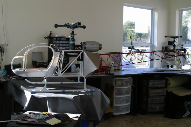
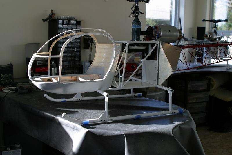
Now we can see where this thing is going. Everything is starting to fall into place and I can see the light at the end of the tunnel
Meanwhile, I have been working on the tail boom and I have powder coated it in Lego red. This was a very difficult process as my oven was too small so I built a cover for the top burners and although it got hot, the losses were so great that I couldn't get the temp to 450 degrees. I had to rotate the tailboom very close to the burners and let the radiant heat melt the powder. It worked!
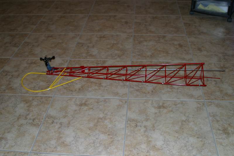
I also coated the tail rotor guard in yellow, an easy job in comparison. Before I coated the tailboom I added another three driveshaft bearings to make it properly scale.
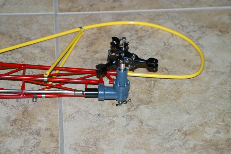
Then I painted the tail rotor gearbox the correct color. I don't want to paint the rest of it as it would mean taking it apart. I did the head while I was at it. I am going to do the driveshaft as well, but that will be a major masking job and then painting out doors as its too big for my small spray booth.
The frame is now finished and cleaned. I hope I have remembered everything as it will be impossible to add things after it is powder coated
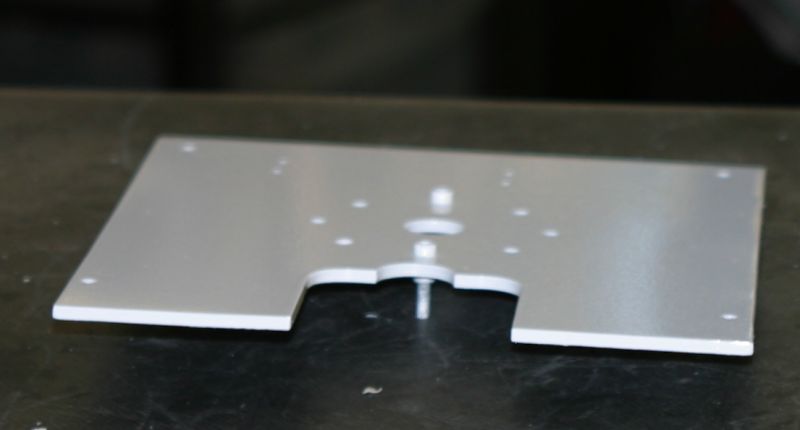
I have been doing some powder coating to get a feel of exactly what is necessary to do flat panels. This is the third try on the top plate. I wanted it gloss, but not too glossy or it would look wrong. Its a function of the temperature of the oven when you first put the piece in. If it is at 450 degrees, then the powder melts and flows to give a nice gloss finish. If you have it cooler, then the powder starts to set before it has flowed
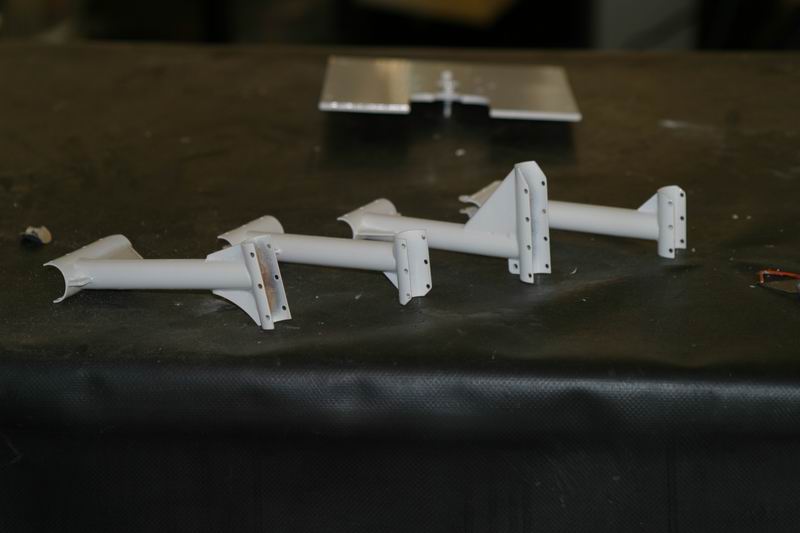
While I was at it, I did the uprights for the landing gear. These were done to a high gloss but with a heavy coat in some areas and a lighter coat in others. Some of the brazing was a little rough and difficult to get at to polish so I put a heavy coat on it.
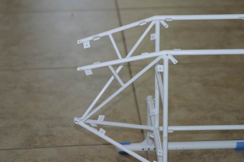
It is such a relief to know that short of a determined attack, these parts wont get scratched. I have changed the front end of the frames a little so as to lower the nose and keep everything in balance. It has been annoying me for a while but it was a major job to fix. I decided it was time to stop procrastinating and get on with it so this is how it will look at the front end.
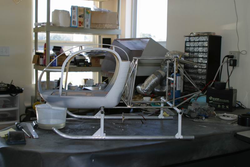
I also think I need to put some tabs on the top tubes which angle down to the tail boom. These will be to hold a top plate in place and I think some sideways support may be beneficial although there is a crossmember which goes straight across the tailboom. Extra rigidity can only be good. While I am at it, I will make some for the bottom angle as well. A couple of days powder coating has brought the model to this stage
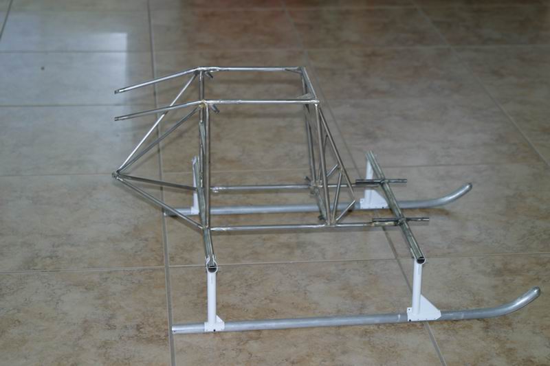
At some time, one of the top tubes at the back of the frame has been bent. Straightening it out has left a small crease in the metal. I got worried that the crease may end up fracturing and eventually break off. These tubes have always worried me as they are unsupported, but when the tailboom is attached and the top plates fitted the structure is super rigid. However, it has been a nagging doubt in my mind bearing in mind the eventual application in competition and the cost of this heli in time and money, I bought some tube 4 times as thick and started again. Cleaning the powder coating off is a nightmare. Paint stripper, wire wool and emery paper finally did it, but the whole frame had to be done as I knew it was going to show where I tried to blend the two together. The new tubes were brazed in placed and were much stronger, but just to be sure I added some 6mm thinwall braces down to the tubes below. While I was at it, I paid extra attention to the alignment of the whole structure and the tailboom. Learn by your mistakes! Finally the top plate mount could be lined up to match the alignment of everything else.
Now the chassis looks like this and it bounces without bending!
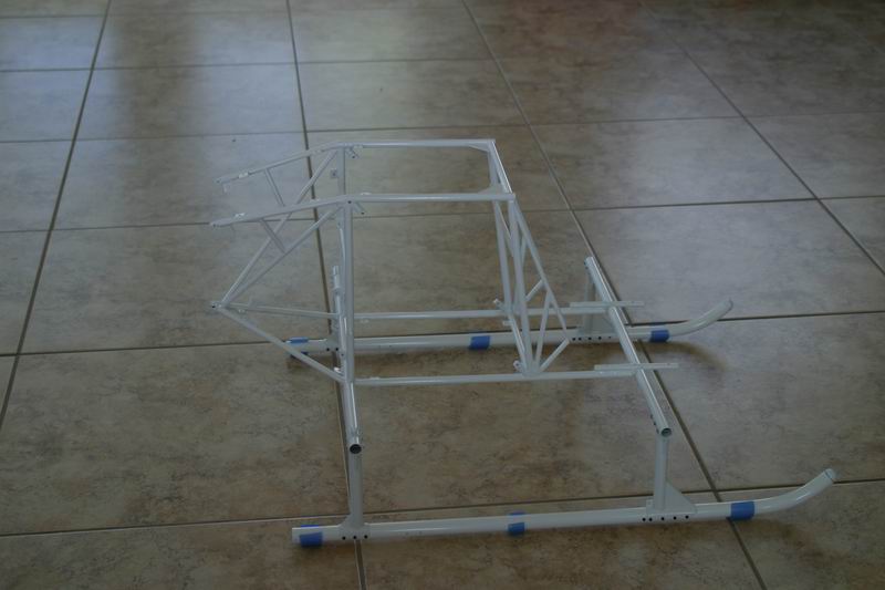
Now I have to remake the rear top plate and the two side panels and then I'll be back where I was a week ago.
Well after a short interlude building another helicopter, I got back on to the Lama briefly. I have painted the tail rotor blades and made new top and back upper plates.
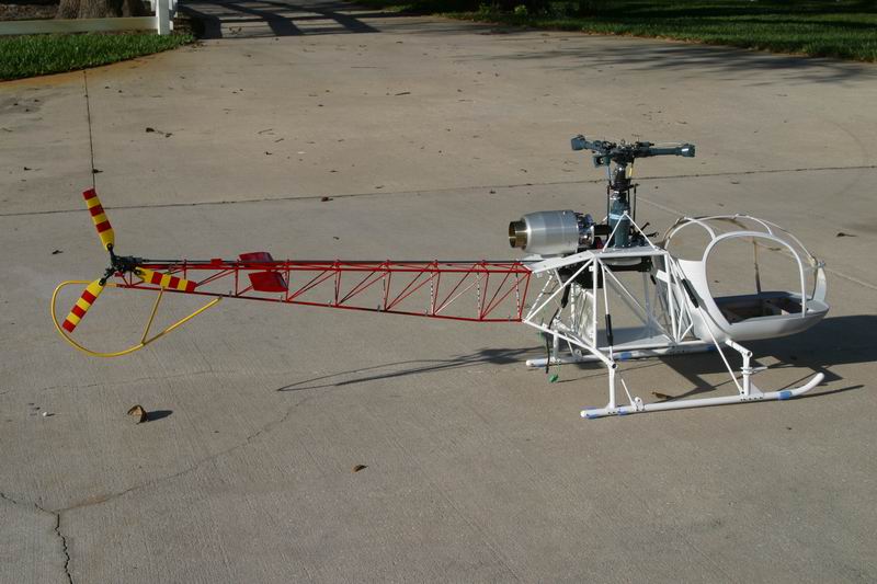
New side panels have been made and painted together with the triangular under panel. These need various things doing to them including clearcoat and a strobe light for underneath. The landing gear braces have been powder coated and their spring dampeners drilled out and fitted. I am running out of things to do. There is one small thing, and thats the cabin! I have been putting it off but time is marching on and I will have to make a start soon.
I have to do the rear light, weights on the end of the horizontal stabs, run the cables to the tail rotor pitch mechanism and get that working and then the tail end is about done.